 |
 |
||||||||||||||||||
|
Blenheim armament Bombs, bombs, bombs...
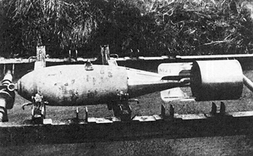
A 250lb GP Mark IV bomb, still nose-lugged (ie unfused), in the standard mustard yellow of the early war years, with tin fins attached but apparently unpainted, sitting on a bomb trolley. In the original, it is possible to read the stencilled bomb type. The sharp end: prime armament
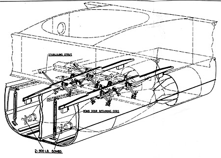
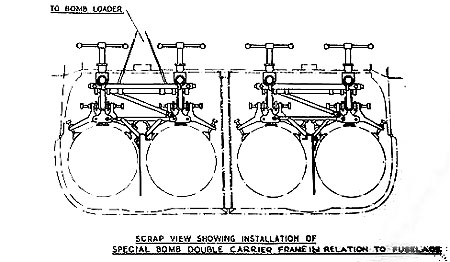
Having devoted a lot of effort in the late 1930s to redevelopment of the Mark IV GP series of medium capacity general purpose bombs, the RAF found it difficult (both doctrinally and in squadron operations) to surrender this smaller armament, let alone accept the relative ineffectiveness of the small charge-to-weight ratios employed (around 30%) and their high detonation-failure rate (10-15%). The size of bomb-bays in RAF aircraft and the perceived chance of a hit were both real considerations in this early period. During 1940 in Bomber Command alone, use of the smaller ordinance (over 2,000 20lb F; over 26,000 40lb GP; nearly 62,000 250lb GP) far outstripped that of the 500lb GP (just over 20,000). By 1941, that Command’s use of ordinance had changed considerably (less than 5,000 40lb GP, less than 35,000 250lb GP), as medium and heavy bombers of greater capacity entered operational service in growing numbers. In the Middle East and Far East theatres, where the smaller medium bombers like the Blenheim soldiered on through 1942 and into 1943, smaller ordinance remained in regular use. It was late 1942 before development of the Medium Capacity series bore fruit, with their higher charge-to-weight ratios of 40% or more and better filling, while the much larger High Capacity series, with ratios in the 80% plus range, took rather longer to perfect. Bomb loading The 20lb F and 40lb GP bombs might be mounted either individually on the external Light Series Carrier (the LSC), or in the Small Bomb Container (the SBC, the rectangular, re-usable alloy canister winched directly to the bomb-bay). The Air Publication records port and starboard wing-root cells for two or four flash (FL) or reconnaissance (REC) flares. Possible internal bomb loads included: 2x500lb (one per cell) or
The diagram (not to scale) shows three examples. 4x250lb, left The 4xSBC arrangement necessitated removal of the bomb-bay doors.
In the Blenheim I, when the bomb load was two 500lb GP bombs, they were carried on two No 2 universal carriers, each attached directly to supports in each bomb cell, hoisted into position with the bomb loader winch.
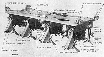
When the bomb load was to be four 250lb bombs, they were carried in pairs on No 1 universal carriers mounted in a frame, again hoisted into the bomb cells with the bomb loader winch. The Light Series Carrier (LSC)
Capacity 4x40lb or 4x20lb bombs. The Small Bomb Container (SBC) The SBC was capable of carrying a wide variety of weapons. It was produced in various sizes: the two-partition 160lb Hudson unit, the 3 or 4 partition 250lb unit commonly used in Blenheims and shown below, and a larger unit used in the Lancaster. Intentionally light in construction and with relatively complex electrical and mechanical fittings, the SBC needed careful handling and storage and was not to be found lying around in outdoor bomb-dumps.
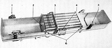
The illustration from Air Publication AP 1664 Bomb Carriers shows the 250lb SBC as used in the Blenheim, viewed from the underside as for loading by the armourers. Key: Forward is to the left. The arrowed instruction inside the empty front partition reads “Bombs to point in this direction”. A single canister of incendiaries has been loaded in the centre partition, located with the aid of the movable partition plate and locating plates. The contents are secured with a single drop bar, locked in its EM electromagnetic release at one end and in the hinge bracket at the other. On release, the EM unit will activate its Type L slip release catch, leaving the drop bar free to fall clear away under the weight of the ordinance. Crews occasionally resorted to dropping 250lb loads “safe” on the ground. The technique for jettisoning SBCs and LSCs on the ground required the attentions of the “plumbers” and rather more care. Once prepared for the required bomb-load, with the correct number of partitions and release catches arranged to match, the container was placed, open side up, in its detachable two-piece loading cradle. With ordinance loaded and retaining drop bars engaged, a separate lifting cradle or frame was then also attached. Next, the loading cradle was used to roll the entire assembly over. The loading cradle was now detached, leaving the SBC “right side up” with respect to the bomb-bay and ready to be carried, by its lifting cradle, to the aircraft by hand or by bomb-trolley. Once winched into place in the bomb-bay, the lifting cradle was removed. The bomb load of the open-faced SBC, however made up, was packed horizontally fore-and-aft into the container. The number of partitions, drop bars and internal packing pieces varied according to the make-up of the bomb load. The maximum load per 250lb SBC was either
For the 20lb and 40lb bombs, purpose-made packing pieces secured the individual bombs as a cluster within each partition. The 4lb hexagonal incendiary sticks came pre-packed in tin-plate boxes or “cans”, with a tear-off lid, 20 per box (80lbs): the entire canister, lid off, fitted into the SBC. In each case, the loaded SBC carried 240lbs of armament. Air Publication 1664 Bomb Carriers, Vol I Ch 3 The 250lb Container for Small Bombs (Preliminary issue 1939) gives a full description of the 250lb SBC, with packing methods and diagrams for the various types of armament. Other Marks of the SBC could carry more ordinance, as described in the Armourer’s Handbook circa 1942 and later, by AL 43 revise of August 1944 for AP 1664 Ch 3. For example by 1944, the Mark IA SBC could accommodate three larger incendiary canisters, now packed with 30 4lb sticks of 120lbs (360lbs per SBC), rather than the 20-pack (240lbs per SBC) used for Blenheim operations. The Mark IX Course-setting Bombsight
As early as 1917, the Air Ministry Laboratories’ development of unstabilised vector sights had arrived at the Course-setting Bomb Sight. The CSBS remained standard RAF equipment for the next 20 odd years. The Instrument Dept of the Royal Aircraft Establishment at Farnborough took over RAF bomb sight development work from 1932. At the RAE, the basic CSBS design advanced considerably and by 1939 the continuous development had seen 14 models produced, in various Marks. Of these, the 1937 Mark IX CSBS allowed for the greater speed and height of the then new monoplanes, while offering electrically driven automatic orientation from the Distant Reading Compass (itself then a comparatively new navigation aid). The Mark IX was produced in 3 models (A, B and C), for use in Bomber Command, the Fleet Air Arm and Coastal Command respectively. The FAA and Coastal Command models were calibrated in knots and were fitted with height bars appropriate to operations at relatively lower altitude than the A model.
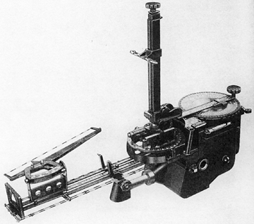
The Coastal Command model. The height bar is the vertical rod, right of centre. Towards its upper end, the adjustable back-sight can be seen. The fore-sight pips are mounted below, at the junction of the wind speed and ground speed bars, above the drift-wires and centre left in the illustration. With respect to position and use in the cockpit, in this illustration left is forward. The Observer or Bomb-Aimer would be at far right, behind and above the height bar, looking through the back-sight spectacles to the pips of the fore-sight.
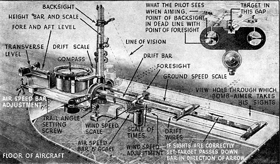
From Britain’s Wonderful Air Force, an RAF sanctioned work of 1942, this illustration shows a somewhat earlier Mark of CSBS, installed over a prone sighting panel in the cockpit floor, with a detailed explanation of the main parts and of the Bomb-aimer’s view (despite the “What the Pilot Sees” tag). In the Blenheim Mark I cockpit, the sight was mounted on the side panel enclosing the control and instrument panel at the extreme nose of the aircraft, for use from the Observer’s forward position on the starboard side, as shown in the 211 Squadron example below.
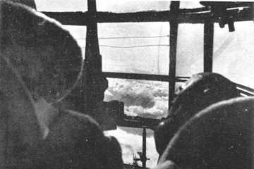
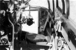
Blenheim I cockpit, photographed from the centre-section well. Above the clouds, the view forward over the shoulders of Pilot and Observer. The Mark IX Course Setting Bombsight can be made out in the extreme nose, past the Observer’s left shoulder. In the upper centre, the cockpit front glazing carries two makeshift wires, purpose unrecorded but possibly a pilot’s aid for low-level attack.
The Mark IX bomb-sight, with the Observer’s fold-down seat ready for use in the run-up to the target. At the start of WWII, the Mark IXA CSBS was the standard sight in Bomber Command and RAF Middle East and Far East. For example, four of the five Groups of Bomber Command were using the Mark IXA in Battles, Blenheims, Wellingtons and Whitleys. In contrast, the Hampden Squadrons of 5 Group were equipped with the newer automatic tachometric sight, under development since 1933. From the Bomb-aimer’s point of view, the precision offered by the Mark IX CSBS was encouraging, provided that as Observer he had first obtained a good wind speed and drift estimate, and provided that the run-up to the target was straight and level, with only flat turns for correction. All this required close co-operation between Observer and Pilot, above the din in the cockpit and the fizz and crackle of the intercom. By these means, in training and on exercises before the war, remarkably good results could be obtained in careful hands. In operations against defended targets or at night, these conditions were difficult to attain and potentially fatal. For this reason, the DRC drive and the azimuth mount refinements of the Mark IX were little used, if at all, in action. It is apparent from various accounts that, despite some attempt at command level to allow for the artificiality of the apparently achievable degree of precision, to the cost of the crews it was well into the war before the difficulties faced in action were properly appreciated and addressed. Guns, guns, guns... The Vickers ‘K’ or VGO The Blenheim was a Bristol product throughout: engines, airframe, and turret all Bristol designed. Initial deliveries of the Blenheim I were originally fitted with the Bristol Type B.I Mk I turret, with a single Lewis .303" drum-fed machine gun. According to Diagram 41 General Equipment of The Blenheim I Aeroplane Air Publication 1530A Vol I, in addition to the single pan mounted on the Lewis, there were no less than seven spare pans racked on the fuselage sides within the gunner’s reach, four to Port and three to Starboard. In total, approximately 400 rounds, for 57 round pans.
By early 1936, development of the Vickers ‘K’ gun (ie the Vickers Gas Operated or VGO gun) had reached a point where it had been accepted as the replacement for the ageing, slower-firing and less reliable Lewis in RAF service. By 1938, Vickers were able to offer drums with 100 rounds of .303in ammunition for use in single-gun turrets and a 300-round magazine for fixed installations such as the Blenheim’s fixed forward-firing gun. Development of a 1,000 round magazine proved difficult and the fixed-installation VGO was overtaken by Browning development and certification.
By 1939, the superiority of the VGO saw the Air Staff decide that Lewis guns were to be replaced with the Vickers model as the RAF service free-gun. Subsequently, Lewis-equipped Blenheims were retrofitted in the field with a VGO in the turret, while the Bristol B.I Mark IE single VGO turret was from then on installed on the production line. In operational use from about mid-1940, gunners in the Blenheim Mark I and early Mark IV generally possessed a single VGO of .303in calibre in their dorsal turret, firing at about 950rpm. Most accounts of this period refer to four spare pans or drums of ammunition (with a nominal 100 round capacity, but in operational use loaded to 97 rounds per drum) and including the magazine already mounted on the weapon, the gunner could offer about 24 seconds of defensive fire, in 100 round, 6 second bursts. While the early 60-round magazines weighed about 7lbs, the later “100 round” drum weighed about 12lbs. Whether conversions to the VGO followed the 1937 practice of seven spare pan mounts on the fuselage is not clear. Some modern commentators have found this state of affairs hard to accept, in stark contrast to contemporary official views. By the late 30s it had been possible to convince the Air Ministry that a gunner could not aim and operate a machine gun from an open cockpit at 10,000 feet in a 180mph slipstream. But having accepted the need for a turret, the standard defence of the time (whether for night or day bombers) stood as a single rifle-calibre machine gun. For day bombers, close formation flying in the 3 aircraft ‘vic’ was the standard tactic to maximise covering fire. Thus the Fairey Battle had armament identical to the Blenheim I: a forward-firing fixed wing-mounted Browning and a single dorsal VGO on a “high speed” pillar free-mounting (but without the benefit of a turret). The Armstrong-Whitworth Whitley originally carried barely greater firepower: the unpowered nose and tail turrets each carried a single VGO, photographs of which show 3 spare drums apiece. Again, early footage and stills of the Short Sunderland I shows the two open dorsal positions each with a single, free-mounted VGO and three spare drums stowed on the vertical framing of each gunner’s station. The Blenheim was a child of its time and its Bristol turret—however limited in punch or field of fire—was at the leading edge of late 1930s defensive armament.
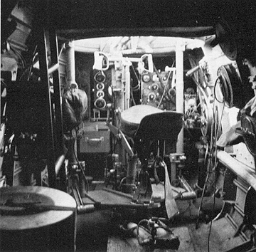
Source: Suomen Ilmavoimien Historia 10: Bristol Blenheim by Kalevi Keskinen, Kari Stenman and Klaus Niska, Tietoteos Publishing 1984 and used by kind permission of Kari Stenman. The WOp/AGs “office” in a VGO-equipped Blenheim I, looking aft. The gunner’s backless saddle-shaped seat is in the centre foreground, lit by the light streaming in through the turret glazing above. The seat was an integral part of the Bristol B1 turret/gun mount, with it's central column and cupola, all raised, lowered and rotated together by hydraulic power. Thus the seat revolved with the turret and gun. The spade grips of the turret gun controls are clearly seen, mounted on the central column. Immediately aft is the usual radio installation of the time: the R1082 receiver and its companion T1083 transmitter (for keyed Morse W/T), plus the TR9 transmitter-receiver Type 9 (for HF R/T voice transmission by intercom, and air-to-air or short-range air-to-ground). Below to the left can be seen the drawer which held the necessary wireless spares. The wireless equipment was operated by the WOp/AG from his turret seat by reaching around the pillar. Sgt WOp/AG Bill Baird was graphic in describing this and the fumbling to tune or reset the radios from the spares drawer. Mounted one above the other on the port fuselage side, at the extreme right of the photograph, are the three spare ammunition pans. There’s no doubt this is a VGO installation. The Finnish Air Force received its first batch of 18 Blenheim Is between July 1937 and July 1938. A second batch of 12 Mark Is was air ferried to Finland in February 1940. VGO equipped, this may be one of either batch. The Finns operated 97 Blenheims in all, both Mark Is and Mark IVs, either imported or license built at the State Aircraft Factory. In the FAF these aircraft gave long and useful service. In the last group struck off charge in 1958 was BL106, an imported Mark I, with 2005 hours “on the clock”. In production, Blenheim Mark IV armament variants were numerous. After initial deliveries still with a single VGO in the dorsal turret, early ( European theatre, 1939) attempts to improve Mark IV rear defence saw introduction of the Type B.I Mk IIIA turret, fitted with twin-VGOs. These required at least double the drum provision: ie 8 drums, 800 rounds, for the same 24 seconds of defensive fire. By 1940 the Gunner in a Mark IV turret was provided with no less than 10 spare drums in immediate reach from his seat, stowed five and five on the fuselage sides, with a further five stowed out of reach abaft the centre-section well. Once the mounting, ammunition tankage and belt path had all been satisfactorily developed, the Type B.I Mk IV dual-Browning turret with its twin tanks of belted ammunition must have been a great relief all round.
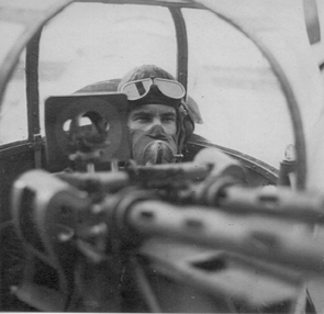
Lindsay and his Mark IV twin-Brownings at the ready. A nice shot, thanks to Les Payne. To cover the otherwise undefendable rear lower-quarter blindspot, a number of versions of rear-firing chin-mountings were offered in production, ranging from a single Browning in a Bristol Perspex blister mount (seen on Len Cooper’s shot, Mark IV Helwan Jan 1942, enlarged below), to the final angular Frazer-Nash FN 54 twin-Browning mounting (shown by Bill Baird’s shot of Q-Queenie en route to the Far East later in January 1942, and by Gordon Chignall’s shot of Z7643 embarrassed in a bomb-crater at Pakenbaru in February 1942, both enlarged below).
The single Browning blister mounting, here on R3733, formerly a 14 Squadron aircraft in Egypt.
The Frazer-Nash FN 54 twin-Browning mounting, on a 211 Squadron aircraft in flight.
The FN 54 mounting again, on a 211 Squadron aircraft in Sumatra. These various mountings suffered several problems, not least the complex belt path (leading to frequent stoppages) nor yet the cramped (aptly named) spade-grips in the now cluttered space for the Navigator: perhaps worst of all, the armament was aimed by periscope. Various occasional modifications to armament were made in the field. For example, in the latter days in the Western Desert, some aircraft engaged in ground attack were fitted with a forward-firing cannon mounted in the Bomb-aimer's position and firing through the forward glazing, which must have made quite spectacular entertainment for the Observer (who presumably withdrew to the safety of the jump seat prior to firing!). Lewis or Vickers A small number of sources report Lewis guns in war-time Mark Is and IVs. At least one of these also claims the wing-mounted gun to have been a Lewis: an utterly farcical proposition for a drum-fed machine gun, offering 6 seconds or less firing. Mentioned just once, in an early Bristol brochure, that proposal was abandoned before production. True, there had been a proposal for a VGO in the fixed wing-installation but this, fortunately, had been overtaken by Browning development. In contrast, the earliest Gladiators briefly wore the indignity of such a ludicrous offensive arrangement while the Browning’s in-wing ammunition runs achieved certification. The “Lewis” story may also have been given credence by the early stages of the (abandoned) Type 143F design, when Bristols referred to “provision for a free-mounted Lewis in the dorsal position”. The Type 143F was never proceeded with, overtaken by Type 142M Blenheim design & production. In the case of Scarf VC (62 Squadron, Malaya), some sources report that his WOp/AG expended 17 drums with his “single Lewis” in their action over Singora in a Mark I. A very remarkable feat. But as to the 17 drums, weighing in at some 200lbs, where were they stowed? Had the Mark IV stowage changes been retro-fitted to Far East Mark Is by late 1941? And the “single Lewis” - was it a VGO after all? Or were Lewis guns still a feature of the RAF in India and the Far East and its more ancient equipment? Curiously, though by the by in this context, pictures and footage attributed as Scarf’s machine show it to have had the wing tips removed. There are a number of current (secondary) sources where the research is simply in error, with photographic, drawn and painted examples of the Vickers VGO captioned “Lewis”. Perhaps the worst example is Purnell’s History of the World Wars volume Bombers 1939-1945, where a beautiful line drawing of a twin-VGO AA mounting is noted as a Lewis. Then again, some sources refer to the free-mounted guns of either kind in the early Blenheim/Battle/Whitley/Hampden period insouciantly as “hand held”, showing a fine disregard for common sense or clarity. In most accounts (including those of participants) and in most war-time photographs, the Blenheim Mark I turret mounted a single VGO with 400 rounds all up (ie four drums), while the Mark IV came to carry either a twin-VGO or a twin-Browning belt-fed turret. Photographic evidence also exists of two marked exceptions: Mark I GA-V of 84 Squadron in Greece with a single Lewis in 1941 (Warner) and Mark I L8396 of 27 Squadron force-landed in Sumatra in February 1942 with twin Brownings (Woodward)! As Bill Baird once wryly observed to me: “Interesting story about the Lewis guns. At Gunnery School they were installed in the Heyford dustbin position, and I must say that I didn't particularly care for the experience one little bit. Your observations coincide with mine, and in the Mark IV one was well aware of the ammo drums beside one's legs. Memory recall - on my first raid to Tobruk with Jock Marshall at the controls, he told me to check my VGO, with a short burst of 10 rounds! On that occasion I was not required to use it belligerently.” Sources Other Air Ministry The Blenheim IV Aeroplane AP 1530B/AL 24 (Air Ministry 1940)
www.211squadron.org © D Clark & others 1998—2025 |
||||||||||||||||||
